A loopback test is a simple way to verify that RS-232 communications hardware is working. You may test a radio interface and your computer's serial port using this method.
A loopback test simply sends data from a port, through a jumper, and back to the serial port. This is typically accomplished using a terminal program such as Hyperterminal. If everything is working, you will be able to type something on the keyboard and see it appear on the terminal window. The signal travels from your keyboard, out the serial port, thru the jumper, back into the serial port, and is displayed on the screen. This tests the port, the level converter device, and any connecting cable. If the loopback jumper is in place, and you do not see your typing, something is malfunctoning or the jumper is not connected properly.
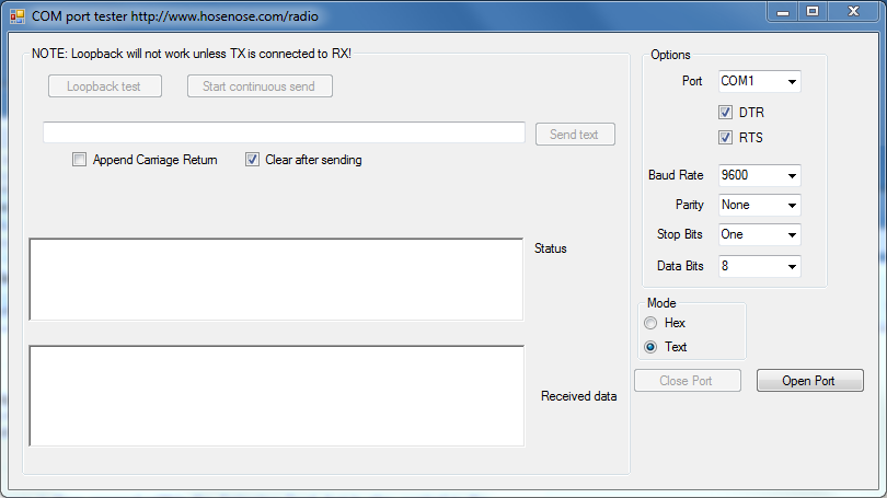
Rather than use Hyperterminal for your loopback test, we recommend using our free one-man serial port tester. The download link is at the bottom of this article. You may save it to your hard disk or run it directly from our server. See the link at the bottom of this article. No installation is required. It will run on any version of Microsoft Windows that has the .NET Framework 2.0 installed.
This utility is great for loopback testing because it has the ability to continuously send data out a serial port -- you do not have to type anything, leaving both hands free to connect the transmit and receive pins on the device being tested. It is also useful for determining which COM ports are installed on your computer, and monitoring data transmitted by other devices, testing baud rates, etc.
After you run the loopback tester, hold the mouse over the various controls to get help.
It is recommended that you first do a loopback test on a known good serial port. This will verify that you have everything set up correctly and are performing the test properly.
Testing the serial port
Select your com port in the port test utility, and click Open Port.
Click Start Continuous Send. This will cause the utility to continuously send the alphabet out your serial port. You SHOULD NOT see anything displayed in Received Data, since you have not yet connected the transmit and receive pins.
Now, short pins 2 and 3 (the transmit and receive pins) of the serial port together. The pins are usually numbered. Get a flashlight and look closely, or use the chart provided here. This chart shows the location of pins 2 and 3 on a 9-pin male connector (the type found on the back of your computer).
1   2   3   4   5

  6   7   8   9
A breakout box is the ideal device for shorting these pins, but they are not easy to find and are fairly expensive. Use micro jumper clips, a larger alligator clip with a nose wide enough to bite both pins, or hold a clean miniature screwdriver over the pins. An RS-232 extension cable that is known to be good can simplify things. Just use the extension cable to extend the port on the back of your computer so you don't have to work behind your computer.
With the transmit and receive pins shorted together, you should see the alphabet appearing in the Received Data field. If this test fails, your port is bad, loopback connection is incorrect, or it is not the port number you think it is.
The ports on the back of your computer are often not labeled. We get a lot of tech support calls simply because the customer does not know which port is which. A loopback test is a good way to determine which port is which. On an ATX tower case, COM1 is usually the uppermost 9-pin port.
Testing the level converter interface
NOTE: A loopback test cannot be performed on the 9-pin Kenwood level converters we sell. They require a connection to an actual radio to provide a small amount of current to the output circuitry.
Level-converter interface pin diagrams
Short the pins indicated with red together. This view is from the outside of the connector, looking at the end of the pins.
Kenwood and Yaesu Big Din
      •
   •     •
      •
   •     •
Yaesu Mini-DIN

     •  •
   •      •
   •      •
Testing procedure
Follow this procedure when testing radio interfaces other than Icom: Plug the interface into the computer port without connecting the radio. Enable Continuous Send in the port tester. You should not see any received data. If you do, there is a short somewhere. Now, short the transmit and receive pins on the radio side of the interface together (consult the diagram on this page). The alphabet should be displayed in the Received Data field. If it does not, the interface or cable is bad.
For the Icom line, which uses CT-17, LCU-3-Icom, and other similar circuits, the testing procedure is different because there is no separate transmit and receive lines to jumper together. The transmit and receive lines are already shorted internally. Just plug the interface into your serial port. Do not plug the interface into the radio. You should see the alphabet being looped back to the port tester. Unplug the interface, and you should not see any received data.
Although we have never encountered this, verifying this internal loopback in Icom interfaces is not conclusive proof that the Icom interface is in fact good. For example, if the 1/8" connector that plugs into the rig were shorted, the loopback test would succeed, but of course the interface would not work. The best way to test an Icom interface is to substitute the interface in a working configuration with the questionable interface. However, another test that can be performed with the port tester is to turn on the CI-V Transceive or Continuous Data Echo feature in the rig. (This is the preferred configuration for LOGic). Set the baud rate in the port tester to the proper speed, then spin the VFO dial or change the mode. You should see data sent by the rig in the Receive Data field of the port tester.
The LCU-3 interfaces sold by us require power from the DTR and/or RTS pins of the RS232 port. Consult the documentation shipped with the interface. The port tester turns these pins on by default. However, you can set the pins manually to test the actual power requirements of your level converter interface.